Building the Flight Path Printer
A GPX file goes in. Two files come out, and a few hours later the flight is sitting on the bench.
The idea
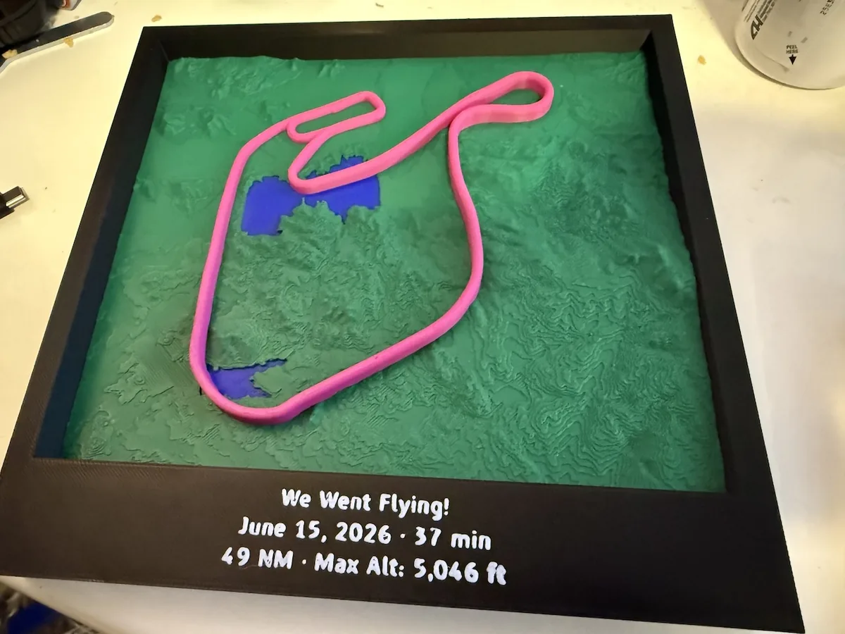
Someone on Reddit had printed the ground track of a discovery flight as a relief map and hung it on a wall. I wanted one for a checkride, and then I wanted a tool that would make one from any GPX file, because a pilot with a logbook has dozens of flights worth keeping and none of them are worth an afternoon in CAD.
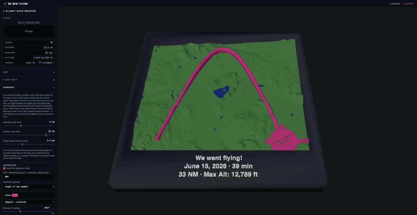
The tool reads a GPX track, works out the map bounds, pulls elevation tiles for that patch of ground, and builds two build plates: the terrain with the flight path standing above it, and a frame to hold the result. It lives at wewentflying.com/3dprint as a page of vanilla JavaScript with no build step and no dependencies beyond Three.js for the preview.
Elevation comes from AWS Terrain Tiles, terrarium-encoded, which need no API key and decode to metres with (R × 256 + G + B / 256) - 32768. Resolution is about 30 m worldwide and finer over the US. A Bay Area flight comes out crisp. Somewhere remote looks softer, and that shows in the print.
Finding the lakes
Elevation data carries no water mask, so the first attempt inferred lakes from flatness: a DEM renders a lake surface dead level, and real ground almost never is across a large connected area. That works. Lake Tahoe comes out blue at 1,897 m. It also has two failure modes, and both of them bit.
The first was Lake Tahoe itself. My flatness tolerance was one number doing two jobs, checking both how flat each cell was and how flat the whole body was end to end. Tahoe measures 1897.2 to 1898.4 m in the resampled grid, so the whole-body check rejected it. Splitting that into two tolerances fixed it: 0.75 m between neighbouring samples, 4 m across an entire lake.
The second was Diamond Valley Lake, which sits beside the airport I was testing with and refused to appear at all. The reservoir filled between 1999 and 2003. SRTM flew in February 2000. The elevation data shows the valley floor because when it was surveyed, that is what was there.
No amount of threshold tuning finds a lake that the survey predates. I went to OpenStreetMap through the Overpass API, which worked and then did not: four public mirrors in a row returned 504 or hung on a single Riverside County query. Water is now read off CARTO's Positron basemap instead. It paints water as one flat colour, so a colour match against the rendered tiles gives an exact mask, using the same tile-fetching code the elevation grid already needed. No API, no key, no mirror to fall over.
A basemap paints rivers and canals as water too, and they arrive one or two cells wide, well under a millimetre at print scale. A feature has to be both big enough and wide enough to survive: it must hold at least one cell surrounded on all four sides by water, which no thin ribbon manages however far it runs.
A path that needs no supports
The flight path is the point of the object, and the obvious way to draw it, a tube following the aircraft through space, is the wrong way to print it. A tube floating above terrain needs supports under every inch, and picking them out of a relief map without wrecking it is nobody's idea of a good evening.
So the path is a curtain: a vertical wall running from the ground up to the altitude line, with a rounded top. It anchors along its whole length, its cross-section is a stadium shape whose cap radius equals its half width, and nothing on the plate overhangs anything. Plate one prints without a single support and needs no glue, because the terrain, the water and the path are three parts of one object that weld at their seams.
Altitude is normalised rather than to scale. A 10,000 ft cruise at true scale would stand a foot off the map, so the flight's own minimum and maximum map onto a fixed band in millimetres. Climb and descent stay relative to each other and the piece stays in its frame.
The curtain also has to clear rising ground, which produced the bug I spent longest on. Clamping each station's top edge to stay above the terrain beneath it copies every ridge in the elevation data straight into the top of the wall, giving a sawtooth of spikes wherever the ground is rough. I blamed the GPS twice before the client pointed at the terrain and was right. The fix runs a rolling maximum over the ground under the track, then a shorter average over that. The maximum's plateau around a peak is wider than the averaging window, so the average never dips back into the hill.
Bambu's 3MF is not the 3MF spec
Getting a multi-colour, multi-plate file to open correctly in Bambu Studio took longer than the geometry did. Most of what follows is written down nowhere.
The generator tag is a gate. Bambu reads its own metadata only if it decides the file is its own, and it decides that from one thing: the Application metadata starting with BambuStudio-. Anything else and the importer logs "found 3mf from other vendor, split as instance", splits the assemblies apart and throws away the part names, the filament assignments and the plates. That check is _handle_end_metadata in bbs_3mf.cpp.
A plate assignment is a position, not a label. The <plate> block in the metadata names a plate and does not fill it. The line in PartPlate.cpp that would assign objects from the file is commented out, marked "we will rebuild later". Bambu works out which plate an object belongs to from where the object is: col = translation(X) / plate_stride_x(), with a stride of plate_width × 1.2. Two plates means putting the second one 307.2 mm to the right.
A mesh is stored centred on its own origin and placed by the build item's translation, so that translation is a centre rather than an offset. A mesh written from 0 to W lands half its own width off and Bambu files it under "Outside". Diffing against a real Bambu project was what finally showed this.
Colour comes from the project config. Once Bambu loads one it ignores displaycolor in the model entirely, so the parts arrive grey unless filament_colour agrees. That config has to be present and non-empty or every plate collapses onto one bed, and it needs at least one real print option: load_from_json pulls name, from and version into a metadata map and never passes them to set_deserialize, so a file of only those parses to an empty config.
The most expensive lesson came from trying to be helpful. Since a minimal config makes Bambu invent a printer and a set of presets, I embedded a real project's config instead, all 569 keys of it, so files would open with the right machine already selected. Bambu Studio refused to open them at all: an error box reading only vector, then "The file does not contain any geometry data".
That message is ConfigOptionVector::set_with(): Assigning from an vector with invalid size. Ninety-nine arrays in that config are sized by the filament count, I had resized eighty-nine of them, and one wrong length kills the load before the model is read. Worse, which arrays those are cannot be read off a single file: on a dual-nozzle machine with two spools loaded, the per-extruder arrays are also length two, and extruder_type is ['Direct Drive', 'Bowden']. Guess by length and you rewrite the printer.
I backed the whole thing out. The file now carries eight keys, and the one that matters is the purge table: flush_volumes_matrix holds nozzles × n × n entries, and get it wrong and slicing stops at "Flush volumes matrix do not match to the correct size". A single-nozzle X1C rejects the dual-nozzle size and a dual-nozzle X2D rejects the single, which is the one thing a file cannot infer about the machine that will open it. So the export asks which printer you have, and that is the only reason it asks.
The real lesson was about verification. I had been checking everything with Bambu Studio's CLI, which slices a 3mf headlessly:
BambuStudio --load-settings "<machine>.json;<process>.json" --slice 1 file.3mfThe CLI applies a project config through a different path than the GUI, and it accepted every file the GUI rejected. My harness could confirm slicing and was blind to exactly the thing I was changing.
The prime tower decides how big it can be
Slicing failed for a while with gcode path conflicts found between WipeTower and Terrain, water and flight path, and I spent a round chasing the geometry before working out that the geometry was fine.
Both plates use more than one filament, so both need a prime tower, and Bambu parks it toward the back of the bed, around y = 202. A piece centred on a 256 mm bed reaches into that band. Each plate now sits hard against the front of its bed instead, leaving that strip clear, and stays centred left to right so it clears the 18 × 28 mm corner an X1C reserves and refuses to print near.
Naming the tower's own position looks like the more direct fix and is not one. Writing wipe_tower_x and wipe_tower_y into the project config makes an X2D print unprintable wherever the tower is put. Front, back, middle, all tried. Where the tower goes is Bambu's business. Leaving it room is mine.
That sets a ceiling on the finished piece. At a 200 mm frame the terrain plate is 183.4 mm and slices; the frame plate is the full 200 and does not. 180 mm is the largest size where both plates leave room, so 180 is the default, and the frame panel reads back the space behind the piece rather than the margin around it.
Sectional symbols, and the variation nobody surveys
A sectional chart draws an airport as a filled circle with the runways through it, tines around it when the field has fuel, and a star when it has a rotating beacon. Printed, the runways are cut out rather than drawn, so the terrain shows through exactly where the chart shows paper. Both ends of a flight can be marked, so a cross-country shows the field it left and the field it reached.
Both are looked up from the track. The nearest-airport search runs against the airport list the site already bundles; the runway detail comes from airports-db, a pipeline I keep on the FAA's 28-day cycle for three other apps. Adding a fourth consumer meant two changes to it.
The first was magnetic variation. A chart draws runways in their true alignment, and NASR leaves TRUE_ALIGNMENT blank for 9,554 of 15,815 runway ends. The designation is always there and is magnetic, so the missing alignments can be reconstructed as designation × 10 + variation. NASR carries the variation in MAG_VARN and MAG_HEMIS, and the pipeline had been dropping it.
The second was the fifth of US fields NASR has never surveyed a variation for. Combined with the missing alignments, that would have left a fifth of airports undrawable. Variation drifts by roughly a degree per hundred miles, so those borrow from the nearest field that has one, flagged so a consumer can say so. 2,854 entries at this release, with the farthest donor 356 nm away out in sparse Alaska.
Runways are drawn to scale, longest spanning the symbol. Which of two parallels sits on top is not in the data, and at Hemet the 2,014 ft strip belongs above the 4,315 ft one, so that is a pair of arrows in the panel rather than a rule.
The symbol that became a pillar
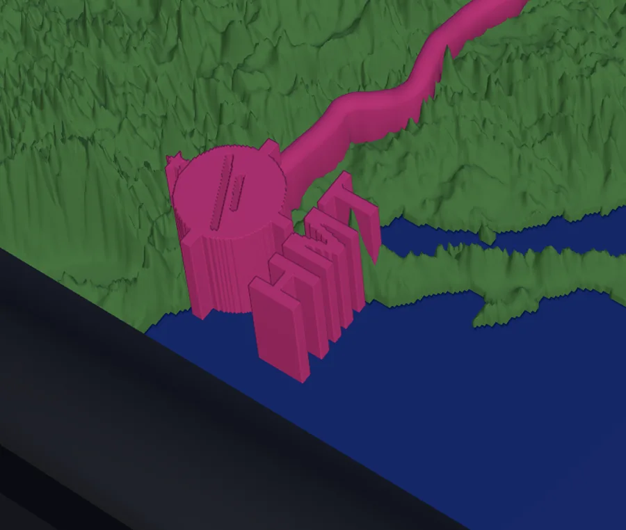
The symbol is thin and the ground under it is not flat, so it used to span from the lowest point of its own footprint to above the highest. A hillside could not swallow an edge that way. Then someone marked a field on a shoreline, the footprint straddled the drop from the lake to the hill behind, and the mark came out several times taller than it is thick.
The fix levels the ground instead of stretching the mark. The terrain under each symbol is cut down or filled up to the airport's own elevation, water there becomes land, and a 0.9 mm skirt keeps the ground from meeting the symbol at a knife edge. The pad follows the lit mask, so it hugs the disc and each letter rather than flattening a circle of countryside.
The symbol then sits at one level on that pad, taking the median of what is under it rather than the extremes, which keeps it honest even where no pad exists: one cliff at the edge of a footprint no longer drags the whole mark upward. It reads as carved into the map, which is what a chart mark should look like.
Ninety minutes off the print
Water started out as a solid, running from its surface down to the build plate. Every layer between the bed and the waterline then contained both green and blue, so the printer changed tool on each one. A lake sitting 10 mm up the relief cost about fifty tool changes on its own.
Water is now a cap 0.8 mm deep, four layers at Bambu's default height, with terrain filling the space beneath it. Sliced with the real thing, a test piece went from 7 h 10 m to 5 h 44 m, and the blue filament dropped from 3,271 mm to 782 mm.
The cap's floor follows each body's own surface rather than a plane, so a mountain lake and the sea each keep their height. It never takes more than three quarters of the depth either, since a shallow sea should not end up with a slab thicker than the water it stands for.
One catch, and it cost a round of debugging. The fill has to be its own part rather than merged into the terrain mesh. Both shells run to the plate and share their shoreline edge at z=0, and a slicer welds vertices by position before it slices, so inside one mesh that edge ends up carrying four faces. My manifold tests compared vertex indices and saw nothing wrong. They weld by position now.