Building Sky Clock
New firmware and a printed case for three Pac-Man clocks from 2018
The idea
In 2018 I built three clocks from the Retro Pac-Man Clock guide on Instructables. Each clock has an Arduino Mega 2560, a 3.2-inch SSD1289 display shield with a resistive touch panel, and a DS1307 real-time clock. This week I connected the first clock to my Mac. It showed Pac-Man and the time, but touch did not work. The second clock showed a white screen.
I wanted a new face with the time, the date, and the positions of the sun and moon. The Mega has 8 KB of RAM, 256 KB of flash and no network connection. The clock has to calculate everything on the board.
Touch and the white screen
Touch failed on two clocks, so I looked for a common cause first. A test sketch printed the raw values from the XPT2046 touch controller. The values changed at random.
The URTouch library clocks the controller at about 4 MHz. The XPT2046 has a limit of 2.5 MHz, and the resistors on the shield slow the signal edges more. The Mega read each bit before the signal was stable. I added a 2 µs delay to each clock edge in the library. After that change, touch worked on both clocks.
I read the flash of the second clock with avrdude. It held about 1.5 KB of code, the same size as the Blink example. The clock program was gone. The bootloader still worked, so I installed the Pac-Man firmware again.
A white screen on a UTFT shield
A white screen means that the backlight has power and no program sent the start-up commands to the display. Read the flash before you replace the display.
The Sky face
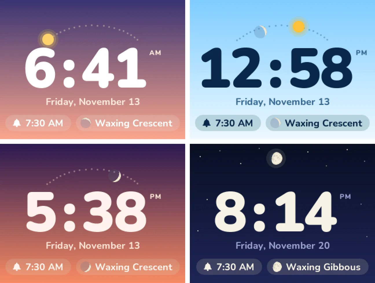
The Pac-Man firmware draws bitmaps with hard edges. For the new face I wrote a small renderer for gradients, rounded shapes and smooth text. It builds one screen row in RAM and then sends the full row to the display, so the screen does not flicker during an update. The text uses the Nunito font in five sizes, with 16 levels of edge smoothing.
The sky color changes with the time of day. The firmware calculates the positions of the sun and moon for my latitude and longitude. The moon shows its phase and its tilt, so an evening crescent leans toward the sun that set. I compared the calculation to the full, new and quarter moons of early 2024. The largest error in illumination was 0.2%.
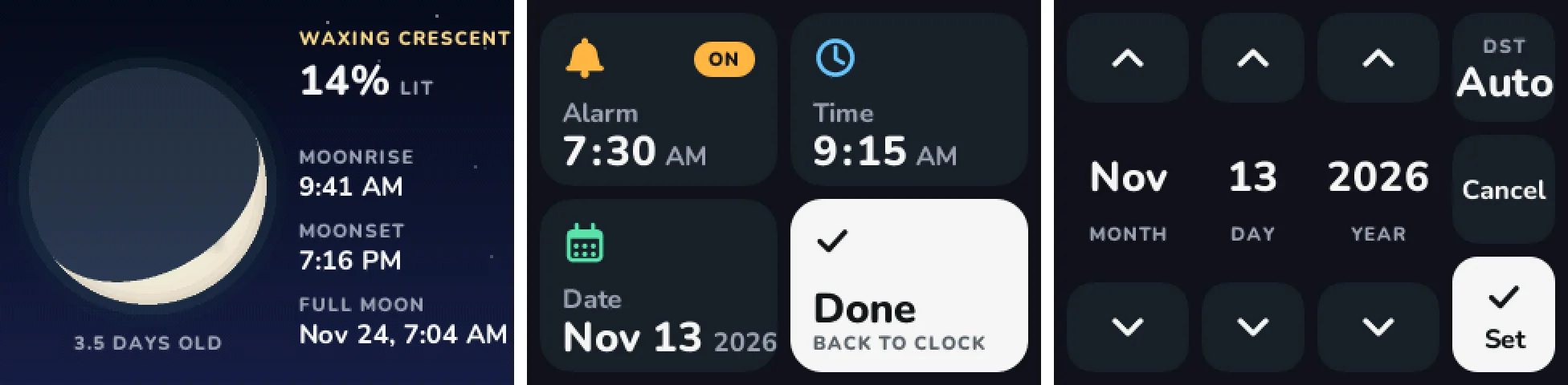
I also wrote a simulator for my Mac. It compiles the same C++ drawing code and saves 320 × 240 images in the 16-bit color of the display. All the screenshots on this page come from the simulator. With it I could check a layout without an upload to the clock.
A faster write that froze the clock
The first version needed about one second to draw the menu and 6.9 seconds to draw the moon screen. I made the color blending and the fills faster. I also replaced the UTFT pixel write with my own loop, which wrote to the display port.
At 9:13 the clock froze. The time did not change, taps had no effect, and white pixels showed along the right edge. A power cycle did not fix it. A touch trace showed correct values, so the board ran and the display ignored the data. My loop held the write pulse for 125 ns, and that was too short for this shield. I restored the UTFT write and kept the other changes. The menu now draws in about 0.6 seconds.
The same evening, the date editor closed in the middle of an edit. A timer value wrapped around, and the clock went back to the main face after each tap. I fixed the timer check.
Test display changes on a spare clock
I have three clocks. Now I test changes to the display timing on a clock that I do not use. Then I install them on the clock on my desk.
Ten faces in the flash
After the Sky face worked, I designed more faces. A tap on the left or right edge of the screen changes the face. The clock keeps the selected face after a power loss.
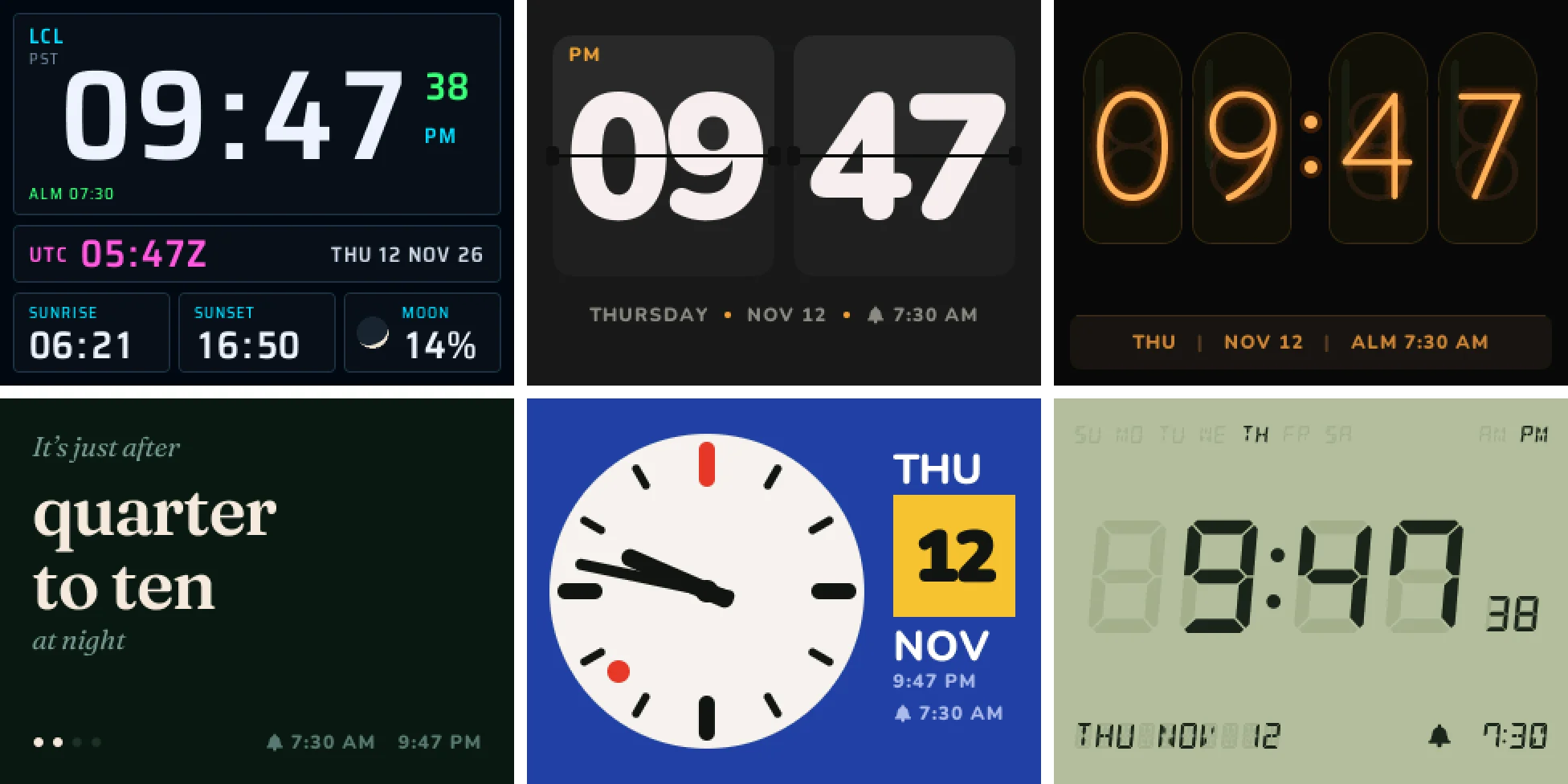
Fonts use most of the flash, because each face has its own large digits. I compressed the fonts with run-length encoding, and seven faces then used 174 KB. After the first upload, the serial port printed random characters. The 118 KB of fonts moved the lookup tables of the Arduino core above the first 64 KB of flash, and the core reads those tables with 16-bit addresses. I moved the fonts to a linker section after the program code. The serial output was correct again.
I added three space faces last:
- Guidance Computer copies the Apollo DSKY. It shows VERB 16 NOUN 36, the Apollo code to monitor the clock time.
- Mission Control shows local time, GMT as the day of the year, and the time since the Apollo 11 launch.
- Earthrise shows the time above the Apollo 8 lunar horizon. The Earth is the Apollo 17 Blue Marble photo, with the phase that you would see from the moon.
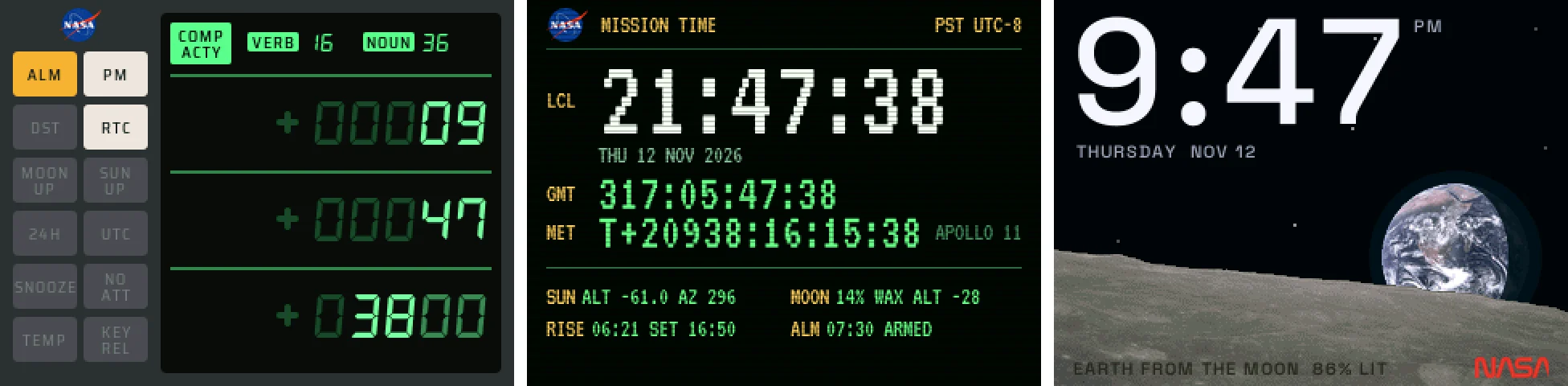
All ten faces use 229 KB of the 254 KB of flash, and 1.7 KB of RAM stays free.
The firmware also sets daylight saving time with the US rule. The real-time clock keeps standard time. The firmware adds one hour from the second Sunday in March to the first Sunday in November.
The printed case
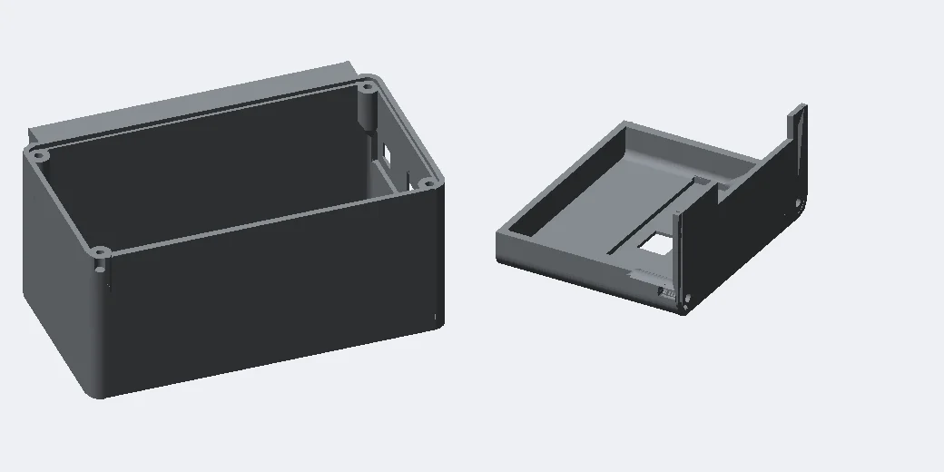
I based the case on a photo of a NASA ISS tracker. It is a grey box with a white front panel and a screw in each corner. The panel has the NASA worm and a data block with the designation, the issue date and an ID number. Each clock gets its own ID, from SKYC-001 to SKYC-003. The box is 152 × 84 × 69 mm. A wedge under the box tilts the screen back 8°.
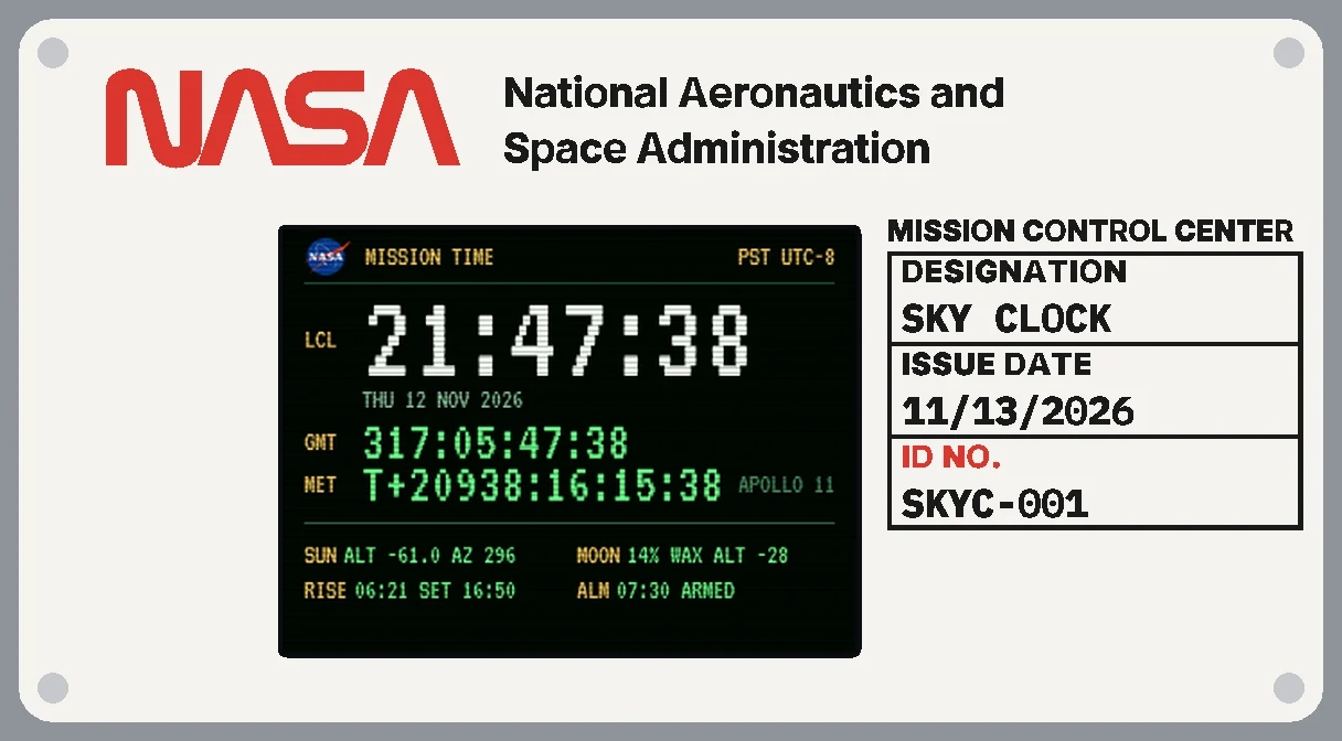
The panel is 2 mm thick and prints face down. The text and the worm go 0.4 mm into the face, in black and red. The color changes occur only in the first four layers, and the rest of the panel prints in white. The texture of the build plate gives the front its finish.
A Python script with manifold3d generates all the parts from my caliper measurements. The left wall is flush with the barrel jack, and the USB jack extends 6 mm past the wall. The old case was too tight for the USB cable. This layout gives the plug more space.
Text size for a 0.2 mm nozzle
A 0.2 mm nozzle needs a stroke of at least 0.4 mm. The script erodes each text shape by 0.2 mm, grows it back, and measures the lost area. My first labels lost up to 25% of their area. With bolder weights and 2.3 mm capitals, all the text lost less than 2%. The NASA meatball failed the test because its stars and orbit line are too thin, so I removed it from the panel.
Next I print the fit gauge and a test piece of the panel text. I print the full case after those tests.